How Do You Calibrate Pressure Gauges and Pressure Sensors?

A simple example of the practical implementation of a calibration can be shown by means of a pressure gauge or a pressure sensor.
The basic reasons for calibrating a pressure gauge are the same as for all other sensors: sensor drift and specifications through quality management systems and guidelines. In short: whenever the pressure measurement is a process-critical variable and has an influence on the product and/or the process safety, the pressure gauge or the pressure sensor must be calibrated.
The practical implementation of a pressure calibration is one of the simplest of all measuring means. The device under test is connected via a hose or directly to the pressure calibrator. The pressure calibrator consists of a pump which generates the pressure and a high-precision pressure gauge – the reference pressure gauge.
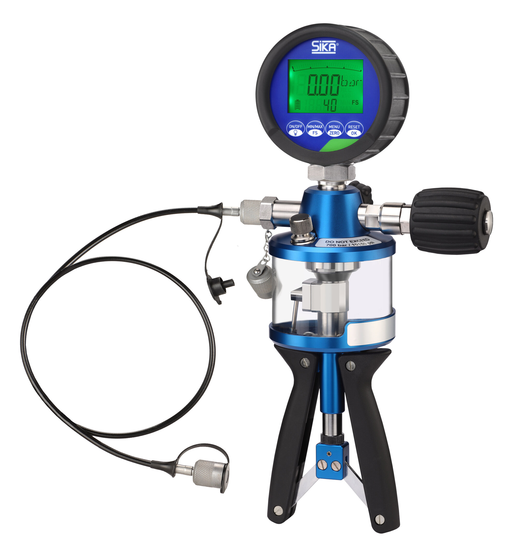
As soon as the device under test has been connected, a closed system has been created from which no further pressure can escape. Due to the pressure build-up via the pump, the reference pressure gauge and the device under test are now acted upon by exactly the same pressure. Thus, a simple comparison of the true value (reference pressure gauge) with the device under test value is possible – the calibration.
A pressure calibration is much more forgiving than, for example, a temperature calibration. Due to the closed system, even a knot in the hose would not change the result. The temperature influence due to changing ambient temperatures can be practically neglected due to the small volume or can be corrected within seconds by the fine adjustment valve.
Overall, a pressure calibration can be carried out within minutes without great expenditure, whereas the calibration of a temperature sensor can take several hours.
Typically, two principles for pressure build-up are distinguished in pressure calibration: pneumatic pumps and hydraulic pumps. Which principle is used depends on the desired pressure range: in vacuum and in overpressure up to 60 bar, as a rule pneumatic, from relatively zero bar to >1000 bar hydraulically.
The differences for the user are that ambient air is used as a calibration medium during pneumatic calibration. As a result, the device under test does not come into contact with hydraulic fluid. The required force is higher than in the case of a hydraulic pump and is therefore typically limited to pressures below 100 bar. In addition, a vacuum can be generated with pneumatic pumps and can also be calibrated in the mbar range in the relative range around zero bar.
Hydraulic pumps use oil, or even plain tap water as a calibration medium, as is possible with SIKA. By using water, the device under test is not contaminated with oil – this is highly important in some applications, for example in the food industry. Since a non-compressible medium is used in the hydraulic pumps, the pressure can be generated faster and with less force than in the case of pneumatic pumps.
Finally, a tip from practice for calibrating mechanical pressure gauges:
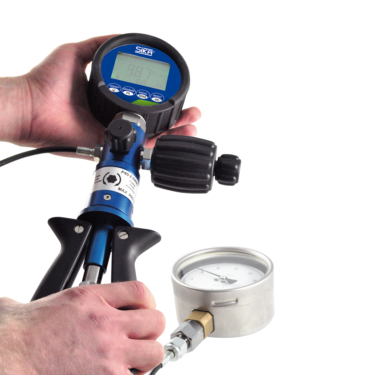
Mechanical pressure gauges are still often used and calibrated in pressure measurements. If such a pressure gauge is now acted upon by an exact reference sensor pressure, for example 10.000 bar, the display needle of the device under test does not stand exactly at 10 bar in the case of a slight deviation. However, since a mechanical pressure gauge cannot display decimal places (as a digital pressure gauge can), it is not possible to determine an exact deviation.
In order to do this, the trick used in practice is to set the reference sensor pressure in the device under test to the exact value and to read off the deviation at the reference pressure gauge. In our example, therefore, the mechanical pressure gauge should be pressurised so that it indicates exactly 10 bar and then read off the deviation at the reference pressure gauge (e.g. 10.058 bar).